 |
| GONG |
Before we begin our evaluation, let's just take a deep sigh and get comfortable where we are. Are we all set? good, because this week as been non stop work to the max.
 |
| Not just a Square, but a Master Square |
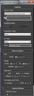 |
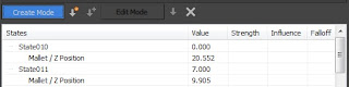
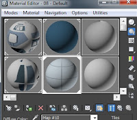
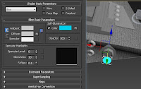
We create the
Parameter here |
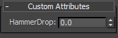 |
| And here the Parameter is |
Let's start with last week, the general exercise we had to do involved the methods of
Rigging and Skinning and the
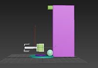
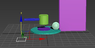
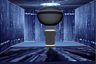
Reaction Manager. Sadly due to the lack of exercise on the former, i have none for this week (though i do intend to do something with bones next week to compensate). The exercise on the Reaction Manager however, proved to be difficult. For starters, the VLE didn't provide the model mentioned in the tutorial, so i had to make my own Gong, i simply chose a Sphere as the animated shot, a Cylinder combination for the Mallet and a Box/Cylinder combination for the stand, i didn't think it mattered about polygon counts or appearance, just as long as it'd animate.
 |
| Devious Thing of Trickery!!! |
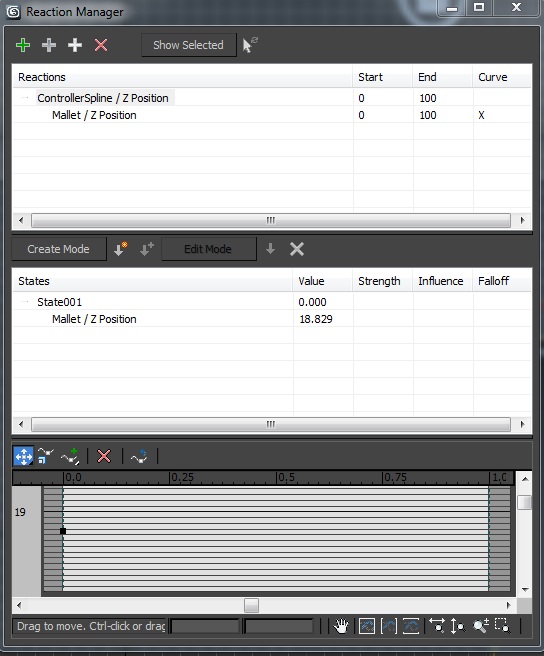
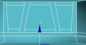
The easy part was mainly making a controller, seeing as it's a Spline (splines are not visible in the rendered animation), i did consider my options when selecting the parameter editor seeing as the setting was on 'Spinner', seeing as my mallet would only drop down and my ball shoot up there was no spinning involved, after some checking however, i did leave it on that setting. With the parameter in place, the Reaction Manager was opened. This was the difficult part.
 |
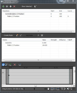
| See the Arrow? that creates a Slate |
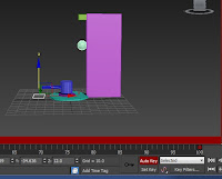 |
The Red Line means Auto key is on, then you can animate
in a more simplistic way via frames |
When you add a Master and Slave to the Manager you have to select what is going to happen, for mine it would be a Transformation>Z Axis (seeing as the Mallet would go directly down and the sphere directly up). What is supposed to happen is that when you change the number of the created parameter and place the model in a new position (so for my Mallet, a few co-ordinates down) while the 'Create' tab was highlighted in the Manager, by clicking the arrow next to it we would create a 'Slate' which then would enforce the animation to that variable point. However, whenever i did this the new slate would have its Value set to 0, plus when i did assign the value to the Slate, when i inputted the value into the parameter (which acts like a time slot, so if i set a position for value 10, if the parameter is 10 i should see the set position different from when the value was 0) the model remained still. It was only when i moved the Controller that the animating begun, meaning that the controller was the one that needed to change value as well as the slaves - though i only clicked the sphere to animate, i didn't make it a Slave - using this information i used the
Auto Key feature to animate the Controller, thereby animating the Mallet and the Sphere in perfect harmony.
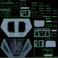 |
| My first UVW :D |
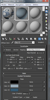 |
| 50 shades of Gradient |
Although the model animated, i do not have a final animation to show you (i am aware that i need to show some animation on this blog, but i'm trying to reserve it for my assignment work), the reasons being; firstly, i don't have the model with me, secondly, i didn't render it and thirdly, had i rendered it into an animation, we wouldn't have seen much as there was no lighting within the model. With regards to the Reaction Manager, it can prove to be handy if used properly and, hopefully, correctly, i must admit that this is one of the toughest features i've encountered within this module and most of what i've done i believe is just lucky accidents or some kind of glitch. However, if i were to incorporate this into my animation, it would probably be used to move multiple objects in time, i can also use it for Camera 'shakes' - so moving a bit to exaggerate the closeness of a ship going offscreen or an explosion - rather than assign the camera to a path, plus it can help with timings - something i should really think about sooner rather than later.
 |
| Not so good on your floors really :P |
Now, seeing as you are all comfortable, i shall move on to the big part; Texturing and Lighting my model.
 |
| In all its Textured Glory!!! |
 |
and the unsettling relationship with lights
begins |
Last week i set myself a target to have at least completed the Textures for all 4 of my models, with 3 days left until that target deadline i am safe to say that it is going extremely well. For such a hefty ask beforehand, i previously planned my times for working (as most of my home time is dedicated to my other module - where i can't use the laboratory computers), i went in early on Monday and Tuesday and have probably spent a time of 15 hours in the labs within 3 working days (Wednesday i took off due to family priorities), with that, i managed to reach about 90% of the way to my prioritized mark.
 |
| TOO BRIGHT!!! |
 |
| Still a bit bright on the top... |
 |
-_-
not bright enough |
 |
| Nothing Normal about it |
 |
YAY!!!
still too bright... |
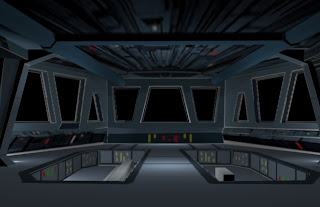 |
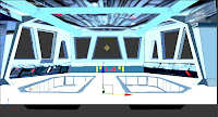
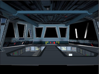
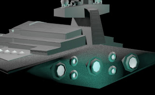
Notice the White Lines? the lights also suggest there
are hallways past the arches, but that's the final right here! |
 |
| Begone Shadow!!! |
 |
| Cells Sell |
 |
A mistake can happen at any time, so always be
prepared |
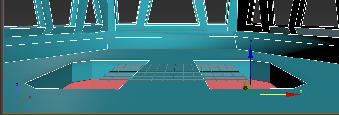
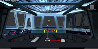
I continued from last weeks blog with my Star Destroyer Deck, after some cropping from the image (referenced in a previous post) and some paintwork of my own i finally managed to complete the UVW. From the image you will see blank spots, but you would have to remember that most of the Deck's bevels and outer faces won't be seen, as a result i left them alone and focused on the visible faces. After assigning the UVW to the deck i worked on the other parts not connected (i later discovered that trying to access the editable poly afterwards will disrupt the UVW unwrap modifier, so in future, convert it to an Editable Poly again just in case). For the models not connected to the Cylinder i had now some options; i could unwrap it all meaning that i'd have a multitude for the pipes (as cylinders would have multiple long faces) and be somewhat detailed, or i could just add a non-bitmap material. For the pipes on the ceiling, i chose the latter and opted for a Gradient material, using the color swatch from Gimp or modifying from it to make it darker, i found that the Gradient material could be used for single-colored materials for future models such as the Star Destroyer. For the Ceilings and Arches i chose to again UVW unwrap; i did this mainly because i wanted to add some of my own detail to it or crop some from the referred image; i did have a bit of an issue with the orientation sometimes (which i could've discovered by selecting a vertex on the flattened UVW rather than a polygon) but overall i had no problems. The final thing to texture was the computers inside the Deck, as the image as rows of this kind i used a Tiles form of material, meaning that the tile line would make the model appear as if there were multiple same-shaped models all in a line (like the computers are in the referenced image). With that done, i had one model complete!
 |
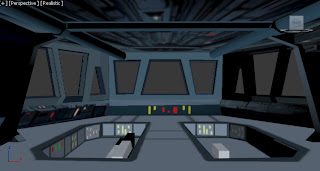
That blue still irks me today, but there isn't much i can do
i do love the walls though :D plus the Omni in the ceiling gap |
At this rate i was beginning to get used to Textures, no longer thinking that there would be a weak point in my 3D modelling, i would later be proven wrong. Seeing as i was still on the same model, i decided to do Lighting - as it would be silly to just leave it only to come back and light it. I began with setting up an Omni light in the Middle, being familiar with omni lights i believed that it would work like most lights; it would brighten up the place but retain it's main color. It would take some time lowering the intensity and changing the main color until i found a well-suited brightness for my lights (hoping to get the same effect i would with the default Ambient light), i did however find it strange that the lights were all outside the cylinder. To light the ceiling i attempted a
Skylight, the light was mostly supposed to brighten up the ceiling and show its texture (which the omni lights failed to do successfully), what i received was extremely unexpecting. It would appear that the
Realistic viewport would brighten up vividly whenever the Skylight was clicked (on any viewport), luckily this wasn't a finite brightness as the light would later calm down to its original form if the correct viewport was selected (otherwise it would stay vividly bright until selected or the skylight was deleted). I later managed to lighten up my ceiling with the help of a
Free Spot light (just a simple spotlight dropping down), it was then where i thought i was safe and decided to render the final image to support my theory.
 |
| Ref - http://www.scifi-meshes.com/articles/images/anselstarwars/01.jpg |
I was wrong.
 |
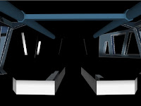
| Not so Camo Now is it? |
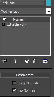
When rendered, the deck didn't light up! The external models lit up, even the faces of the deck that should not be seen lit up, but the required parts of the deck didn't (plus they were vivid). It took a long while to find the solution to the problem, i asked one other student who couldn't find out the problem, i tried my tutor but he was off on Mondays, i only knew one thing, the outside of the Cylinder lit up perfectly fine, the inside didn't. After trying to find interior lighting tutorials i discussed my issue with another student (Sam Sparks i think his name is, excellent modeler who has helped me out a few times now), he later revealed to me that my faces were the wrong way round, thus explaining why the inside wouldn't light up. He told me there was two ways to fix this; i could add a
Shell modifier which made every face 3D, meaning the texture would show up both sides at the risk of an increased polygon count, or i could add a Normal modifier and select the 'Flip Normals' option, but it could mean that i'd have to detach and reattach each face of the deck. After briefly looking at how high the polygon count would be if i used the Shell modifier (it was over 1000 for a circa 80-100 polygon model) i immediately chose to use the Normal modifier. I chose this mainly because, although it could be tediously long, i am still moderated on my polygon count. Luckily for me, i only had to flip Normals once for my Deck, after reassigning my lights (three Omni and a Spotlight) the render outputted clearly, i grouped together the lights and then added them to the overall group to complete the Deck, by grouping it all together, it means that it would be easier to merge models into one scene, meaning i don't have to light so much. Although the model rendered, i did make another discovery, the White Lines around the deck wouldn't disappear. I later discovered, due to it only being on the models i UVW unwrapped, that these must be the voids of where the green lines of a UVW would be, meaning they were filled with white, i didn't mind as much afterwards seeing as they'd be masked by blinking lights and the model itself only being used for a short time.
 |
| They render fine every time i try... |
 |
God said "Let there be light!" so the
Athiests did it themselves |
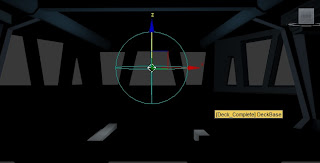
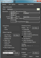
So that was one complete (if you haven't already, take a coffee break, we're just over halfway), i still had three more models to do. For my next model (as i sent my most recent models to my Student e-mail to be used) i decided to use the tools i just learned on a similar model; the Engine Room. As commonly referred to by one of the students as 'the one with the big sphere' i used this because i would have the same problem as the Deck with the faces being the wrong way round, to worsen the issue, there were no windows or holes to allow any light from above, casting a shadow over the main sphere. I discovered though that i could make the Sphere impervious to shadows by selecting its
object properties, with the properties selected if you untick the 'receive shadows' checkbox on
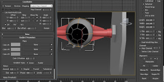
General, you can stop the object from having a shadow, you can also stop it from making shadows if you untick 'cast shadows', throughout the lighting phase though, i did return the sphere to its original state. When texturing the Engine Room i only used the UVW unwrap once and it was to texture the surroundings (using the image from the mood board which i referred to when producing the model in the beginning; it's link is - http://www.theforce.net/swtc/Pix/dvd/zs/rotj/ds2core.jpg) however i did discover that, despite the polygons not being selected for this map, the tower in the center of the room found its way into the UVW. To avoid issues i moved the faces that overlapped it and left it untextured, afterwards, i detached the whole tower from the Cylinder, further aiding my grouping as well as ease of texturing. After detaching the tower, i decided that i'd need to detach a bit more so i could map colors without the need of unwrapping, so i detached the inner ring of the sphere and the thin platform that held it, meaning that i could texture them separately. For the two detached elements i used a Gradient map again, using the map on the sphere ring while i used a Tile map on the upper part of the tower, but for the Tower itself i opted for a
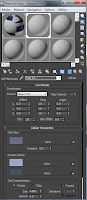
Cellular map. A Cellular map, with the parameters edited, made a more 'dirty' and interior appearance to the tower making the illusion that the model was inside a ship, it was here i also remembered to Name the textures, so to avoid forgetting what you textured if ever you need to change it or you've lost the bitmap file. With my second Engine done, all i needed was three Omni lights (grouped but unfortunately unnamed right now) and a grouping to complete the second Model. Although i don't approve so much of the distinct blue in the far back of the floor face, i do concede that it could be masked by the explosion that would occur during this scene. Next would be a next challenge; my first model - the Star Destroyer.
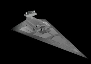 |
| Doo Doo Doodoo Doodoodoo Do Dodoo |
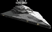
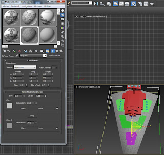
The Star Destroyer would prove to be easier to texture than it was to build, firstly i removed the reference planes i used to create the model, i did this because it took up polygon space, plus it would be a little bit more difficult to merge the Star Destroyer model individually with the planes also in the merged file. After searching for about 20 minutes for a suitable Star Destroyer reference, i decided that i didn't have to be extremely detailed on this (as most of the details you couldn't see anyway), so after choosing a reference for coloring i decided to use the
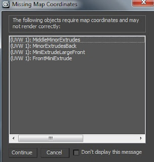
Perlin Marble material onto the Destroyer's base. At first glance, Perlin Marble looks more like a Camouflage material, however, with the variables modified it can be presented differently, i chose this over Cellular because i wanted to try a new material, plus the cells, although less evenly spread, were much longer and less blotchy than in a Cellular map. For the Star Destroyer i used Three UVW unwraps; two for the platforms and Tower, and one for the small model between the Generator Spheres - i did crop the front of the Tower face previously, but due to it not matching the color i changed it again. Due to my detaching (as the lower parts of the platforms were darker than the above and unwrapping it as a whole would be gigantic), i get a pop-up whenever i render for the Star Destroyer saying that some UVW Map Co-ordinates cannot be found, as this has only happened today i intend to bring it up tomorrow in the following tutorial (where i will do work later mentioned on top of naming my Engine Omni lights and creating a model that involves bones). After the UVWs were done, i used three different shades of Gradients to light up the rest of the destroyer, the next texture though would prove to be vital.
 |
| Not ideal, but take what you get |
In the animation, one of the key scenes depict the Engine lights on the Destroyer flickering on and off, to get a light effect i decided to use a material for the occasion. First i cloned the inside faces of the engines as a new object (creating Cylinders for the smaller engines as they wouldn't allow a create polygon, this upped the polygon count by about 35, keeping the count to be around 1,500 polys), then i added a gradient material of bright blue onto the object and ticked on the Default setting of the material the
Self-Illuminate checkbox; this would mean that the material will brighten up, i intend on using this for Blasters as well, meaning all i would need to do on the scene is hide the bright objects for a few frames and then unhide to make a flicker effect. To ensure it lit up, i added three Omni lights around the engines of the same color. The Destroyer then only needed Four Omni lights to light it up, after being grouped together and rendered, the Destroyer was complete. I was pretty happy with the texturing of this, seeing as it was all done by hand, i know that the call for detail is limited for close up shots, but there are only little of those in my animation.
 |
A couple of Wings, Some Lights
and i'm straight into Animation Baby! |
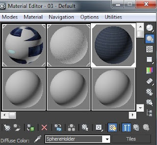
Our final (yes, almost there) model of the day was the Tie Fighter. As the day was nearing its close, i didn't get to finish Texturing yet, however the fighter is overall the simplest to build and texture. After searching about 20 minutes again for a suitable reference, i decided that i'd work by memory (though i do intend to find one for the wing pattern) and use a similar color to one of the swatches i took off Gimp with minor alterations in the 'select color' box. I first removed some unneeded edges at the front to get an easier UVW for the front Window (which i detached from the main sphere), after mapping the UVW (which i didn't even need to flatten), i used a
Sphere Map on the rest of the pod using a lighter Gradient Texture (i used the same gradient on the arms) and began work on the wings. After i removed some edges from the Wings my time had come to a close, meaning that it is still undone, however, i already have a UVW prepared for it - knowing that after i complete one, the other should be fine - meaning that i am almost as good as done on the matter. The texture on the Tie is simple, meaning that it isn't hard to be content over it, i believe i won't need much with Lighting but only time will tell.
That will be a story for next week, now breathe, take it all in and remember; although it took you about 10-20 minutes to read it, i had to write it - and i can tell you now, it's taken about 3 and a half hours!!! Till next week!