 |
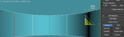
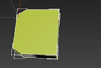
It's faint, but there is a brown line there
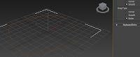
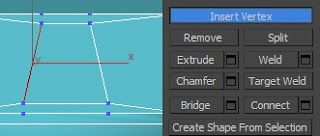
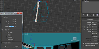
See how it's smooth and not corner
(top one, Bezier is a whole different reason) |
This current week has dawned the realization that there is about three weeks until my assignment meets its deadline, with me still creating my fourth model while others start animating it is clear that once more i am behind on my work.
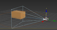 |
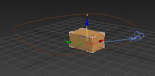
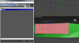
the Target camera didn't quite click into the box for
some reason |
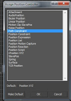 |
path constraint allows
this to be possible |
However, as i discovered today, my efforts are rewarding; having achieved a high mark for the first assignment regarding the previous three models and the first six weeks of blogs. It does concern me how behind i am, seeing as i only realized that we had to texture our models last week on top of animating, however the results does give me confidence that i am doing things that work.
Moving onwards, this week's tutorial exercise was to make a target camera follow a line. This will be very handy in my animation for my scenes, especially if i can apply the lines to my models - i will discuss more about animation later.
 |
| Set Path moves the camera to where the Spline Starts |
The tutorial was quite straightforward for me as it was mostly applying a target camera onto a line, i started with an ovular spline for the path. When using the line feature of a spline, i found selecting the 'smooth' radio button instead of 'corner' allows a more circular shape - evidently because the corners are smoothed out into curves - this will allow the path to be more fluent and not so jagged when it animates.
 |
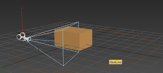
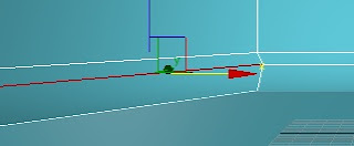
| a few frames down the line, and look where the camera is now |
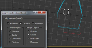
After locating the Path Explorer and then selecting the spline while the 'Set Path' button was clicked, it becomes important to remember where you started - personally, as i already knew this, i would create the path
after the model you are going to animate, that way you can start the spline where you want the camera to begin. Afterwards you can watch the camera loop as it follows the line, or change the viewport to see the animation first hand, however, when this animation renders there will be no Lighting so not much will be seen.
 |
| making faces flat was a semi-good decision |
 |
| Yoink! |
Before the practical we learned about certain aspects of camera angles and animation - which we are assigned to discuss about for ours. When i look at the animation's storyboard i do believe that some effects can be incorporated in there, i also believe that some camera angles could also be utilized. Starting from the first scene, we are using an Objective view to see the Engine Room, but we can also use a path and Target camera to exaggerate an explosion and make the camera shake from it. The second scene shows a back near-low point view of the Star Destroyer's back, with its engines flickering on and off which is a good show of anticipation, this would be followed by the side view of the ship and the beginning of a tilt. The fourth scene within the Deck could also apply the path and target camera, as the camera follows a more Subjective view of the Star Destroyer tilting down to the terrain. The fifth scene will then revert to a cross low point and Dutch camera angle looking up at the falling Destroyer angular but almost in direct range, this would emphasize and exaggerate the fall the Destroyer is undertaking, plus the Tie Fighter jerking a little when it is clipped can anticipate the instant exaggerated corkscrew that commences as the fighter leaves the screen, a path could also be used for the Camera to almost jerk out of its way. The sixth scene will be another Objective view, but at a slightly superior angle as the Destroyer crashes, possibly exaggerating as its nose drags against the terrain before it's behind falls with it. The final scene will zoom out a little and be more level, making a brief pause to anticipate the explosion that ends the animation.
 |
| Almost looks like a TV |
 |
of course a little moving was required before
the Vertices were directly beneath/above one another |
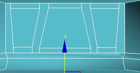
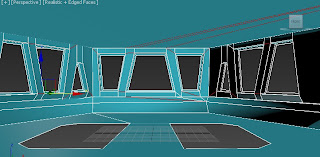
After finishing the exercise, i went straight back to working on my Deck. After considering my perspective of the root image i decided to not inset the Top polygon of the Cylinder, instead i decided that it'd be reliant on textures and additional objects (much like the flooring and computer monitors). So, starting with a new Cylinder i re-approached the work, i started with removing some of the edges so the front three faces would be flat; my intention was to use that so i could create the windows easier (as the root image has them in sets of three), to then make the computer monitor effect underneath, i pulled out the lines so the two lower faces were angular, i made it three polygons so it could be easily textured, plus it'd reduce the polygon count.
 |
| Damn Trapeziums ¬¬ |
 |
| notice the little bit outside to make it 3D |
 |
| I say again, damn Trapeziums! |
 |
| Luckily i had cookies beforehand |
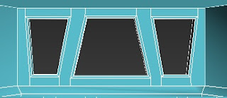
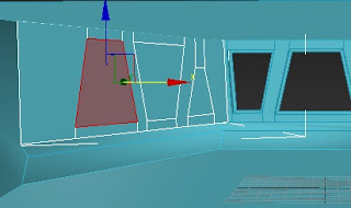
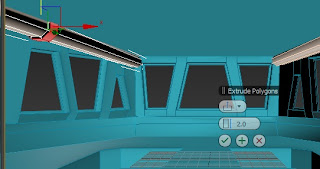
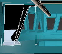
Now it was time to begin working on the Windows. I started with the windows as they are the main asset of the Deck, what happens outside will also explain the havoc that animates inside, and approached this by combining familiar tools together. I began with a process of using Inset, once i was content with the gap i would move the vertices to make the main Trapezium shape. Given that the polygon would appear abnormal, i decided to add Vertices directly above and below the ones that made the Trapezium, connecting the lines together so i could remove the horizontal ones, this was preferred because it made it easier to repeat the process with the adjacent polygons that had been created following the production of the trapezium, this process was repeated to make the first window. Once the faces were complete, we needed to make holes so we could look outside, originally i thought about just deleting the main polygons but then i remembered the minor 3D effect you get on windows (the frame being a bit outside the glass), as a result, i used a combination of beveling and insetting the three polygon faces and then deleting the face itself, this gave the effect i was looking for.
 |
| What we take, we return looking slightly different |
 |
| definitely utilizing all the viewports |
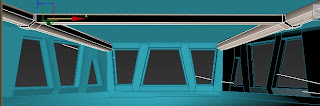
The next two windows were structured the same, so it was evident that all i would necessarily need to do is complete one and mirror it to the other side. However, what i didn't expect was that when i started to move the vertices, they would move at an angle. Although troublesome, it was something i had to deal with - i had also attempted detaching the element, but it had no effect, if i were to repeat this though, i would probably have created a new face altogether, despite the chances of having to guess the size and angle of reattaching it to the Cylinder. Once we completed the Windows and placed them back to where they used to be, we used the Attach tool to attach them back to the primitive, then we applied the same Bevel-Inset-Delete method to complete the three windows.
 |
| Offset is now my friend |
 |
| Edges however... |
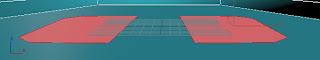
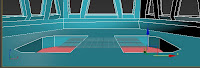
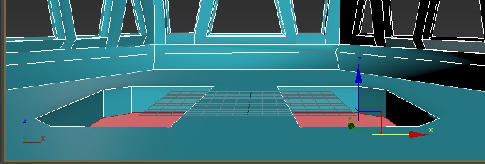
Next was the flooring, the floor on a deck is lowered compared to the main floor, meaning that there needed to be 2 D-shaped gaps in the floor. Despite considering Inset once more, i decided to do a 'cookie cutter' approach by using a Modified Cylinder (as it had more sides than a box) as a Boolean. Once aligned one of the objects by the y axis, i used the Mirror tool to create the other, using the Offset to create a decent gap. Although i have had previous concerns over Offset, i came to accept it as it became more handy in my work. After the Boolean cut the gaps, we met a common aftereffect, due to the cutting 3DS Max had created more edges, increasing the polygon count in the process, this meant that i had to remove more edges to be efficient, however i kept some for the benefit of keeping some logical polygons intact. After the holes were made they were filled by the Create Polygon tool, this then quickly lead to a negative Extrude to create the lowered platform.
 |
| Fill the gaps |
 |
| and down they go |
 |
Evil things are drained through these pipes...
evil things |
 |
| Best friends :3 |
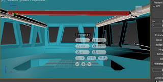
Afterwards was the Piping on the ceiling, made primarily by two large cylinders. Using all my viewports to get the correct view i then used the Mirror tool once again to copy the Cylinder on the other side. Using Offset again, this time the Mirror tool was copying the Y axis, meaning that the Cylinders will come closer to one another the further away from the screen they got (giving a more 'long' effect). Within the root image is a ring around the pipe, meaning that the Local Normal Extrude takes place once more, by joining both Cylinders together via Attach, i could make both cylinders extrude at the same time. A struggle commenced when i realized that the 'hole in the roof' stated last week was actually a raised ceiling, this meant i had to connect two faces from the extruded ring of the cylinders. Originally, i attempted extruding one and then welding the vertices together, this failed dramatically as the vertices refused to weld, instead i decided to take a chance and hope that another method was as logical as its name.
 |
| and my other best friend; Local Normal! |
 |
| just when i thought i was done for... |
To connect the two faces, i used the
Bridge tool. I had previously heard someone explain to another about using the bridge tool, however i was barely listening, my hope was that the tool did exactly what it said on the tin - bridge the gap between faces. My first try was pretty confusing, i selected the two faces but the bridge had twisted itself, believing that the lower edge of one face needed to be connected to the top edge of the other, however, knowing that the process worked i attempted to find a solution. The solution was found by activating the picker on the lower row, meaning that i could select the two polygons manually, this worked perfectly but raises confusion over why the other didn't.
 |
| SuperBridge! to the rescue |
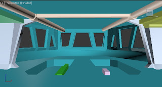
The final process was creating more parts of the lowered ceiling and a somewhat curved corner-wall (suggesting that the sides have hallways leading to other rooms). After even drawing the model on my hand, i found the solution of modifying a box and pulling out its edges, in addition, the separate creation created the illusion that the wall was attached to the pipe ring, even though it was not even adjacent to one another. Adding a couple of boxes lead to the lowered ceilings and computers inside the lowered platforms, this was mainly because it is not the main focus plus the surfacing would be left to textures. Afterwards i grouped the models together and completed the Deck.
 |
| it looks attached, but it's not |
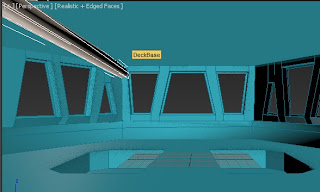
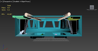
Overall the Deck was 310 polygons, considering the complexity of the shapes i feel this is fairly good. The difficulty of the model may not have been as high as the previous three models but it definitely tested my skills and got me using another foreign tool. Overall completing the model in the basis of a week with this detail is a pretty impressive feat, and it means that i was ready to begin textures.
 |
| What? you didn't want a weapon of mass destruction!? |
 |
| Ta-Da!!! |
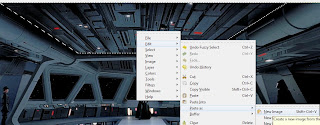 |
the lack of PS licences means that Gimp is our only
alternative |
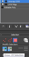 |
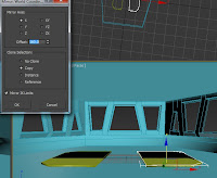
The Modifier must
be in that order |
 |
| Face to face! |
 |
| It's gonna be a long night... |
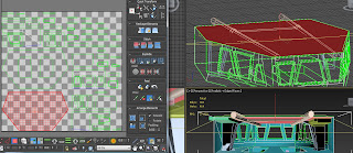
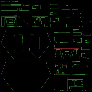
Texturing is safe to say probably my weakest skill in 3D Modelling, so i was personally dreading it. After asking around some questions, i began to work on the Deck (as it was the only up to date version i had on my USB). Despite there being many large polygons, i found that trying to map detailed images could be risky - so i decided i would use the UVW unwrapping method to place some of the detailed images onto the model and apply some via painting through GIMP. To crop the images i opened them on Gimp and created a new layer (so i didn't ruin the main image), after drawing a border i could use the magic wand tool to select the area and then move down a layer with the same selection area which i could copy and then paste into a new image, saving it as a BMP to preserve quality. To start the Unwrapping, i needed to add the UVW Map unwrap UVW modifiers, after many attempts i was reminded by a fellow student to use the 'grow' option to access all the polygons (or else the image wouldn't flatten). Once the image was flattened i kept the window open so i knew which face was which (as some were rotated to fit), after rendering it and saving it as a PNG, i could later edit the borders on gimp using layers once more. I find this to be the simplest solution for the main cylinder, but i do also believe that some textures may not need unwrapping.


No comments:
Post a Comment