Wednesday 31 October 2012

Evaluative Blog Week 6: The Halfway Mark Reached

Many would consider throughout my blogs if i was actually going to be able to complete the work by the deadline. And, like i have so many years before,  i have laid those doubts to rest.
The X-ray meant i didn't overdo the extrude

Overall there were about 6
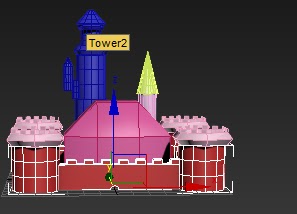
Groups in a Group
like inception...but not inception
Dumdumdum dumdada dumdada
Dadada dadadum dumdadum


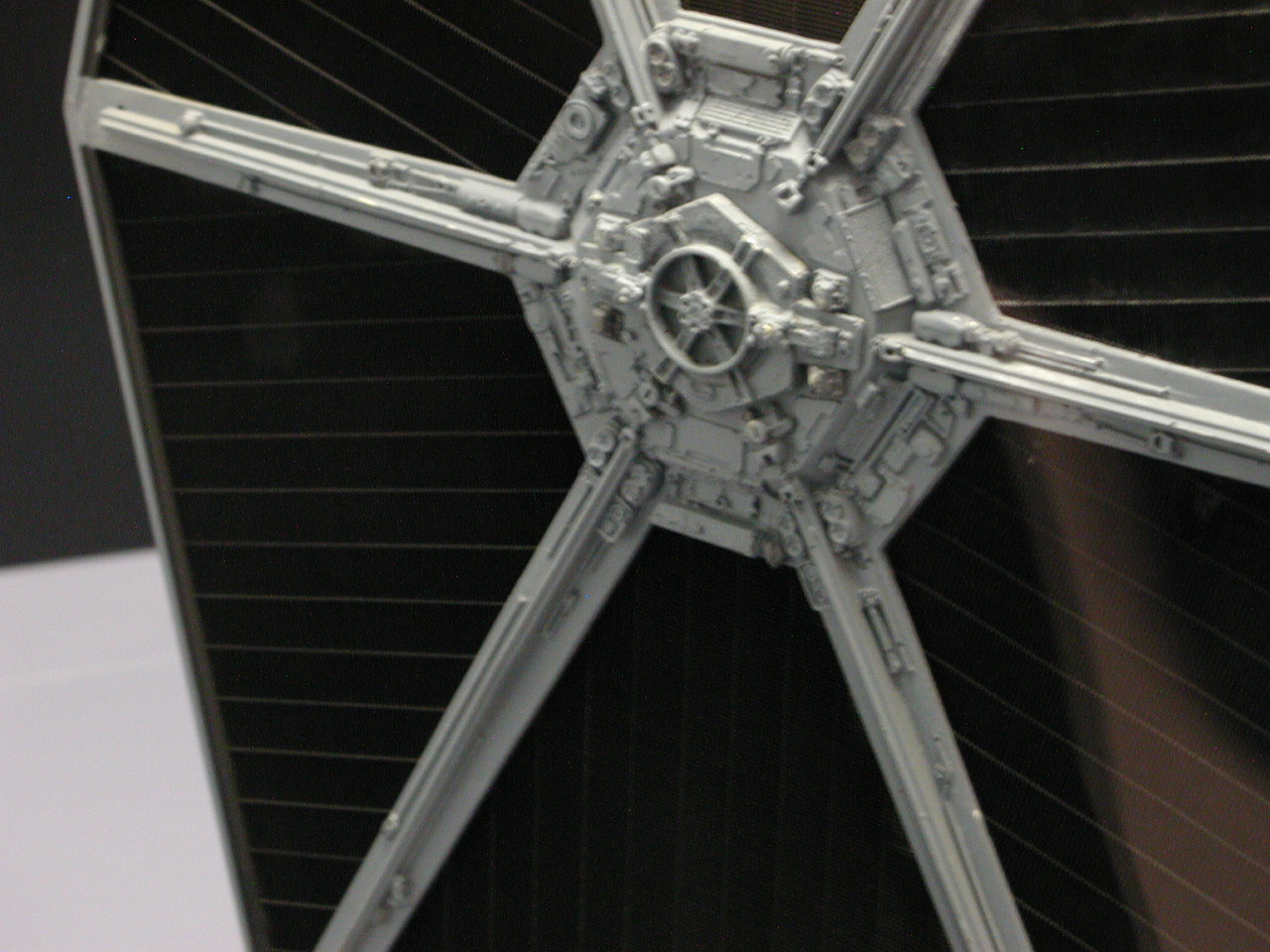
I finished my Star Destroyer in the Weekend. Following from last week i began Extruding the splines. The process became a simple flurry of adding Vertices and Lines until i made the correct shape - the X-Ray dynamic in the Labs really helped with the Shapes. Then i extruded them via Polygon and continued with the next face, given that the extrude was to scale with my reference. I decided that Extruding the platforms was best suited as the Planes were already at a correct Angle, the larger platforms were Extruded first as the smaller and detached Platforms were less recognizable aboard the ship.
i later cut off that bit after the tubes
because i didn't want to Boolean
the Wing
Once i completed that i used the align tool to match it up with the other set of planes with the main body; i decided that i would Attach the main tower via a Boolean and then Group it with the Smaller Platforms Group. I chose this because the storyline shows a Crash, and it gives me the opportunity  to possibly animate the tower collapsing. After grouping it with the platforms i then grouped it with the Body, finalizing the Ship as a whole.
Imagine my joy when i realised i was about halfway done
Just keep Spinning
Reference -
http://www.theforce.net/swtc/Pix/Xbradford/TIE_Fighter_wing.jpg
The Polygon Count was discovered by pressing the + on a viewport, going on xVeiw and 'Show Statistics' - or the shortcut 7 - would show the polygon count seen in the images. For the Star Destroyer, the tally counts at 1,387 Polygons, including the two sets of Schematics plane leaves it to count 1,379. Although the count seems pretty high, if you take into account the detail and size of the ship you can see that this is a very reasonable number; I have had my fair share of deleting edges to reduce the polygon count and i have taken account the involvement of Three Spheres - trying to balance quality of primitive to quantity of Polygons - both of which i knew would increase the polygons, however, i have also excluded many items on the ship such as additional barely visible extrudes, railings on the back and details in where the engines are. It is these details, which i have ignored in favor of texture playing its role in creating the illusion that there are primitives there, which have made the polygon count be half of what it could be.

Moving on to the Tie Fighter, i decided early on it use Tubes rather than a Cylinder to replace the Torus. Only needing to make one of each wing - due to the involvement of the Mirror Tool speeding things up - i took my time judging the size and shape of things, later adding a modified Box and using a Boolean to match the Arm together. Once the Arms were Mirrored (twice, seeing as increasing the Offset made the Mirror Copy thinner) i grouped them together and started on the Wing.

Insetion
I did debate a lot which
Primitive to use here
Pew Pew!
Only Vader rode the Bow Tie Fighter; because
Bow Tie Fighters are Cool


The Wing of a Tie Fighter appeared basic; a Thin Cylinder modified into a Hexagon. I used the Snap Angle tool to get an easier and more precise rotation and stretched the Primitive to its correct size. However, as there was no reference for the other side of the Wing, i had to go find another reference via a Google Search. Following that i decided to use the Inset tool (after being confused by the Outline tool) once again having to modify via Edges to get the correct size. I extruded the face and repeated the same process on the side that the wing attaches to the ship, on the other side i only extruded once, using a Modified Cone and the Outline tool to get the correct shape - then connected via a Boolean and the Mirrored and Grouped as Wings. With the polygon Count pretty low i decided to work on the Blasters - i debated using them as there were small and possibly costly in Polygons; however without them i lose the possibility of animating lasers from it. I used the align tool to align a cone with both top and bottom faces Extruded onto a modified Cylinder (making sure they had the same amount of sides so they fit) and used a Boolean to create the Blasters as a whole and connect them to the Tie Fighter's Body, this was done because it didn't increase the polygon count, if it had; i would've undid the command and left it as a grouped set of primitives. The Blasters finalized the Tie Fighter, leaving it all to be grouped together as a whole.
Although it looks like an addition outside
Inside the Primitive it looks like there's a hole
To Quote Homer Simpson "D'oh!"
to think the smallest things
can take the longest time
The Polygon count for the Tie Fighter is 234, minus 3 Planes meaning the ship is 231 polygons, which is considerably lower than the Star Destroyer. Although i could've limited the Polygons by removing the blasters, i did refrain from making some shapes exact to be polygon efficient - also taking into account that the Fighter itself will not get many if at all close-up screentime.

You Beautiful little thing!
What the Animation Will Show


The final Model to be handed in the for assignment was debated between an Engine Room or a 'Cockpit' of the Star Destroyer, i quickly opted for the Engine room as it is where the first scene takes place. I took inspiration of the Engine room from the image on the Mood Board (the bottom one). From that i modified a Cylinder and cut 4 of its faces so i could get the indoor feel. To create the illusion of there being a massive pipe linking from the ceiling, i used Inset and Extrude once more, i also used that on the lower face so that i could have a central point for the main engine. While Extruding and adding Larger Cylinders via Boolean, i discovered that my lower floor Extrude had caused the underneath to have a gaping hole - increasing the Polygon count; unfortunately, i discovered this too far in to undo the action however i did admit that i should've used the Inset as a Reference and used a Boolean of another Cylinder to create the central tower.

How Modellers See It
So, Who Wants to Go Trick or Treating?
http://livemusicphotography.info/wp-content/uploads/2008/10/img_7252_hdr-600px.jpg
     The main piece of the Engine room was evidently the Modified Sphere, i managed to get its shape by scaling the top half of the sphere and moving the edges closer so i could extrude the faces - although i've come to realise that Bevel was a safer option. The final addition was to add the two larger 'Hangouts' of the room. The left Hangout was a simplistic by-eye scale and Boolean of two Cylinders and a Cone, however, the Second involved a Pipe that angled and went into the tower. While creating the main part of the Second Hangout, i became frustrated with how sometimes the Polygons extruded outwards and sometimes they just all moved one direction, it was here i discovered that by clicking the top icon of the mini pop-ups when you select the Extrude Option that you can select it to 'Local Normal', this makes the Polygons Extrude outwards, or in my case Inwards. When matters came to the pipe i decided that i had to modify a cylinder by rotating the bottom face, later pulling the rest of the tube to create the shape. The first two efforts failed as i had too little and too many columns of Polygons, the third time i managed to create the pipe effect and stretch it into the Tower. I used a Boolean with this into the Engine Sphere but did not connect it to the Tower; this is because using another Boolean will considerably increase the Polygon Count and  that it would all be a single Primitive - which is highly not recommended. Overall the two Primitives were grouped to complete the Third Model.
http://farm4.static.flickr.com/3555/3295756624_c7fe7713ca.jpg
I literally had to raise the roof


The Polygon Count of the third Model rose to a round 430 Polygons. Despite being larger than the Tie Fighter, its size and use of a Vastly sized and Modified Sphere does explain the high count, however as mentioned before, the gaping hole does add slightly to it. Overall though i believe it is a suitable model -seeing as the original image has more detail which can be down to texture within the model - and that trying to reduce the Polygon Count more could otherwise hinder the Model as it did in the early stages of the Star Destroyer.

And That completes the three models due for Friday 2nd November.
However, we are not done.

Our final Model for the week is the Decayed House. 3 weeks late but at least it is complete.
Like Butter in a Knife
Just like a Cookie Cutter
...Damn now i want Cookies
The Angle added to the crookedness
Creeeeaaaaakkkk!
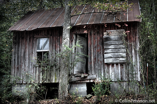
For references on the House i used the two images shown that i collected from Google, i then started out by shaping up a conventional house from a Box. I used additional boxes to make Bricks as support underneath the house to make it look tacky, and then went a step further by using a Slice Plane. The Slice Plane was used to cut the faces of the front left Brick Supporter to make it look broken or sunk - by deleting the polygons made by the slice plane and creating a new one in its place - i then decided to stretch the vertices of the House so it had a crooked look to it. To give a towering rail feel to the roof, i used the Chamfer tool so i could drag the higher edge outwards. To create the gaps inside the roof, i used a Boolean Subtraction method by modifying many Box Primitives (creating extra edges along the way) into the shape that would make the roof look broken. For the Door, i used another Boolean Subtract but then modified a Vertex or Edge to make it look like it was unhinged or falling off, however, i do think now that a separate primitive would've worked better. The Windows required a Bevel before i deleted a face - the other window was split into 4 so i could remove 1 face and not the entire window - this gave the broken window and abandoned effect to further show its decay, this was supported by Boards made by thin Box Primitives. The boards were grouped as a three for the left window and angled with the Snap Angle feature on the right hand Side, to finalize the house and show the gaps, i detached the back wall polygon and changed its color so we could see where the gaps are. The Decayed house was concerning early on into the Module, however i think the increased knowledge of tools helped me into being more confident in the work.

Mainly For Show, not mandatory
Look how creative i was with names
The Purple is the Back Wall, the green are the back bricks (had to boolean
the front because of the crooked angle - which sadly you can barely see...)
Anyway, this is the halfway mark! Thanks for all you who read this and are not
on my course; now i better hope these light hearted captions don't affect
my grade. Happy Halloween!

Thursday 25 October 2012

Evaluative Blog Week 5 - Ultimate Progress

The week has had a lot of stressful work in it.
this gets rid of the fade
I have primarily focused on creating my Star Destroyer at home, trying to learn from my mistakes i am still trying to be less harsh with the polygon count.
I would later use Align so it was
an exact copy
My work returned on making the main engines of the Star Destroyer, however, i realised that my Desktop computer wouldn't be the same as the Laboratory Computers. My first problem was when my viewport started constantly fading to black on realistic views (Wireframe was fine), after many forums i found the solution (after downloading the Maintenance Update that is - which helped me actually load 3DS Max).
Autogrid is easy to
find
My Second Problem became a much more important one, where the X-Ray feature (Alt+x) wouldn't operate on my computer, meaning i had to seek an alternative of creating a copy of my Reference Plane to create the additional placements of my Ship.
Removing the lines the second
cone made means that i save a few
polygons
Using the additional plane, i was able to use the Autogrid feature to place the primitives neatly on the back reference, i used this mainly because that would make a perfect scale and it could show me how many Polygons i could get away with. I used a Cone for this mainly because i was familiar with it; although i do regret not using a Tube for most of my cylinder or cone-based creations. After using the Align and Boolean  Union tool, i removed edges to reduce the polygon count. I then Cloned (Shift and Move Primitive) the engines to make three of them - meaning only the x and z axis needed to be altered. Once complete, i aligned them to the original plane to be placed with the Base Pyramid (i tried a Boolean but the shape changed).
Think of the Polygons...
Welding became useful at times
     My work on the main tower was the one that took it's toll. The basic Boolean for the larger platforms seemed simplistic enough - where some Welding was involved - but the smaller Deflector Shields (the small orbs on the top) became the difficult ones. A Sphere in any shape usually means high Polygon counts; especially with spikes sticking out the top. To reduce polygons yet again, i Extruded certain points of the sphere and used a Boolean to stack it on its podium. the Centerpiece for the tower became a difficult combination of extruding and adding/removing vertices; when the first half was complete, i tested the Mirror Tool to see how it worked. Although it does the same thing, i still prefer to clone and rotate Primitives, seeing as the Mirror Tool can make it difficult to tell the Primitives Apart - as they are merged together.
CLONES
There's an easy way and a hard way
of things; somehow i  always seem
to pick the Hard Way
     My Mistake however was applying the entire tower as a Boolean, leading to edges being made and then deleted and lines that refused to Weld together. After searching for a version with the primitives not in a Boolean, i discovered there was no copy/paste format. What i did find, on the other hand, was by Selecting Element on the Sidebar, i could move the Primitive. I then discovered the Detach tool to separate the Boolean, this left Holes in the main shape, which made me have to create a polygon to fill the void - i later chose to delete the entire face and draw a new one instead. Instead of using a Boolean, i have instead Grouped the tower together (twice, as i have with the large and smaller engines).
Mirror Mirror on the Floor
Some of the most useful things
are found by accident
My next piece of work is probably the final and most difficult part; the raised platforms. After much deliberation i decided that using a Spline and converting it into a Editable Poly would be the best method. After finding which platforms would be first raised, i cut off the additional details and already placed them onto the Star Destroyer Base - but moving Vertices mainly, however i do intend on using the Snap Angle tool - my next part is extruding the platform and then grouping the ship overall.
Soon i had to detach the sides
by making them their own
polygon and using 'Detach'

by removing the lines on the face
of a sphere i reduce polygons
and make it easier to stretch
I would say this is 85% done
Between the time i have done the Star Destroyer i have also began my work on a Second Model; the Tie Fighter. The Fighter itself became as clear cut as imagined; editing a Sphere to the correct angle, utilising the X-Ray vision i do not have at home and pulling out faces to create the shape. I do later intend on using the Mirror Tool once more and also work on my Engine Room model. If there is time before the hand-in, i will do a Decayed House.

Monday 22 October 2012

Storyboard


You will have to pardon my quick-sketching style, but this is the storyboard of my Animation. When i play it in my head it reaches around 28-32 seconds so i can manage it in the 30 second marker.
I will explain the story anyway within further detail.

1) "External Shots fire at the Engine Room, destroying the Engines" - An external enemy ship will off-screen fire at the main Engine Chamber (which i am adapting from the Death Star's engines in the mood board). The shots will further cause explosions signalling the destruction of the engines.

2) "Engines on the Star Destroyer Flicker then turn off" - An in-atmosphere Star Destroyer will start emitting some smoke (optional) as the engine lights will flicker on and off like a light bulb about to burn out, showing the external effect of the previous scene.

3) "Camera Switches sideways as the Star Destroyer Stalls! The ship then starts tilting downwards" - The ship will encounter a dramatic stall from the momentum that the engines could muster in its final moments, the stall could be followed by a dramatic change in the music (again, optional). After a brief stall, the ship begins its nosedive into the ground.

4) "Switch to cockpit showing the ship tilting down" - The cockpit was a late addition to the animation. The cockpit will show the falling course of the Star Destroyer, many alarms and red alerts taking place during this drop to signal panic within the ship.

5) "Star Destroyer Drops towards Camera, a Tie Fighter clips the ship and spins out of the screen" - As the Mighty ship falls in a towards-the-screen fashion, a panicked Tie Figher will try to escape the vicinity, only for its wing to hit a part of the Destroyer and, with one less wing, proceed to corkscrew out of the frame followed by a spiral of smoke.

6) "The Star Destroyer Crashes" - The ship hits nose first into the surface, the direct hit from the nose causes gravity to raise it so that the back can also land, meaning that the ship will flap a little while crashing, presumably causing a little drag and indefinitely creating flying debris

7) "The Star Destroyer Explodes" - Once the ship has become still, a brief pause is made before the ship gives way, exploding from the center as debris rain around the crash area. The scene will later fade out to end the animation.

I'm sorry that this took so long to post, other priorities have made me forget about this. I will also add the physical copy of this to my assignment (it'll be the shortest looking assignment i've ever handed in).
Furthermore, my progress has increased, i am half way on my Star Destroyer but there is still much to do. Although, having seen complete works from others i still find myself to be both polygon strict and probably a little out of depth. However, what matters is that the work is done, and Done it shall become!

Friday 19 October 2012

Mood Board

The Mood Board in it's glory
As you will notice from the mood board, the main circulation is around Star Destroyers and Tie Fighters. From the Storyboard you will also see the sense of how the two engine rooms add to the relevance of the animation.
The General Theme of the mood board is War, as the ships are war ships in the Star Wars Franchise. You may also see from the abundance of the Scene from Star Wars: The Force Unleashed that another theme is Drama and Crashing. These explosions signify the climax and grip of the animation i am going to do, to not make it boring and lose meaning. The Engine room will complete the trinity of models i will hand in for 2 Weeks time, most likely by creating a Cylinder and removing some of the Polygons or by a Half-Circle Spline that has been Lofted and removed of its rectangular Polygon.

Evaluative Blog Week 4: Calamity!

So the fourth week of the 3D Modelling has not been the smoothest of weeks. Overall a lot has gone wrong and not much has gone right, however, a lot of work has been done.

You will find this schematic on the
Mood Board Also
Regarding the Decayed Village, i have decided that it is best to work on my Assignment Models as a priority over the task - which itself has proved complex and difficult to know where to begin. Furthermore i have decided the models i am going to use and the order i shall do them.
The models i used were confirmed by my Storyboard, after timing myself playing the animation in my head i have recently been able to get close to 30 Seconds. The Storyboard will be posted as a single Blog Post like this one, this will also be the same for my Mood Board (alongside descriptions of images and translating my poor handwriting for the Storyboard).

The scaled sizes made the Model
easier to shape inside the planes
My first Model of choice is the Imperial Star Destroyer i have fondly mentioned beforehand. As it is the largest and the prominent model of my animation i decided that this was the one to do first. Using the references from Star Wars Wiki Wookieepedia i got schematics for two of my models (as you will see on my Storyboard, the other model that is mandatory to be handed in for the 2nd November does not require a reference) and added them to planes, all of which had to be of equal scale to one another. However, this required some editing on Gimp and the Side View to be stretched only a few pixels longer.
The more i think about it, the more i wonder if the
Pyramid was the most suitable choice
Inserting Vertices doesn't
have to be on the selected
Line
For the base of the Ship i decided to use a Pyramid, it's square face would be the diamond area for my Engines to be places - i later discovered that using a cube would prove to be a much easier method. I then decided that to reduce the Polygon count and to increase detail, i will use Vertices by using the 'Add Vertex' tool on the Edges Selection Pane and remove the edges to get the correct shape. I would later extrude the polygon to the correct scale of the references.


This happened quite a few times...
In adding the Vertices however, i found myself reediting points because i had either selected the bottom vertex and not the top or mistakenly altered the z-axis, causing the ship to look wrongly morphed. It later came to my attention that by striving for as little polygons and as much detail as possible, i had gone too far - as it is supposed that all edges are met with 3 or 4 points, compared to my 1 or 2, causing the lines i made to be extruded (seen through by the x-ray method of Alt+x) act like a separate primitive.
As a result, i intend on trying to be less strict with the polygon count and start again on a previous version, i shall also avoid repeating my mistakes on the other models. To justify my mistakes though, i only did it so i could improve my grade - which is not a crime - overall i believe that although there is a balance between polygon efficiency and detail, it is indeed difficult to stay in this balance.

Notice how the middle bit is darker
That's not supposed to happen
Did Not Want, Do Not Want
This week's exercise was Texturing. As stated with the Derelict Village the exercise may take a sidebar to the Assignment Models, however, some texturing skill is shown in applying the schematic images to the planes. Regarding the exercise, texturing seems simple enough, but being too clever about it can lead to confusion.

Thursday 11 October 2012

Evaluative Blog Week 3: Catching Up

The third week of using 3DS Max has been a mixed bag. It was only until Sunday that my Desktop completely downloaded the program after being burned to a disc (which i asked my Lecturer to do last week). During the time i have found myself becoming more and more comfortable with using the Program.


Anchors Away!
Last week showed the introduction of Splines, a feature that further aided the building of a model. The actions of a spline appear to be easy, if you remember the ways to select the area between 2 splines for extruding. This week focused on the Lathe Modifier, a tool that - alongside the use of planes for direct references - will become useful when modelling for my Assignment.

Splines, Lofting and Boolean methods
were used to create the walls
With 3DS Max running, i took it upon myself to work on the previous exercises. Modelling a Wheel at novice level was very simplistic with the general knowledge of the primitives and the action of cloning an object by moving it's original while holding the 'Shift' Key - a feat i discovered early in the test process as it mirrored the creating methods in the Virtual World Second Life, which i had to work with last year. The overall outcome of the wheel was good, however if i were to do it now, i probably would have used both a Boolean method to reduce the polygons and the Lathe Modifier so their was a distinct difference on the Helm's handles. (At the time 3DS Max has struck an error in activation, so i will post a picture of the wheel tomorrow).


Pretty Nice Castle says the creator
A Boolean with a small cylinder was used to do
the subtract method and create a doorway


Aligning X and Y together as they are both center
Last week's task was to create a Castle with 4 watchtowers and a door. I found the modelling tasking yet enjoyable as i relished in using the new methods of design i had been taught in the previous weeks. Using Splines, when i knew how to extrude it, was simple to use and sped up the design of the castle walls. Using Boolean functions also became helpful, although i did notice that to use the Union method of Boolean the shapes cannot be exactly the same on the y axis. The creation of the door and merging the castle walls with watchtowers were all down to Boolean methods, another tool called Align was also used a lot to stack primitives atop of another. The align tool was something we also learned about last week, proving useful when i was making towers and 'crows nests' on the castle. Although the lecturer stated to go one at a time with aligning the axis i found it much quicker when stacking primitives to align the x and y axis simultaneously - as the z axis would have modifications of where the primitive would be aligned (Maximum/Minimum). My opinion on the align tool is similar to that of the splines, it is easy to use but if you forget a small detail it can become difficult.
Aligning was used here too, plus i limited polygons
for rigidness

This was a different use of
Aligning by changing the
points of alignment
Additional schemes i had discovered while using 3DS max is reducing the polygon count by using 'remove' while selecting single or multiple edges/vertices. By the use of removing lines, i could make ridges around the castle and keep a minimal polygon count. However, the use of cylinders does hinder the amount of polygons you can use, causing a conflict of smoothness and poor rendering or rigidness and slightly novice models. Another tip that was presented to me was using the Autogrid tool, however i was only introduced to it after i had done the castle - meaning i will do it next time.

Less polygons, Less Problems

Grouping was also a method we used
I haven't seen much gain or loss by it yet however
This week's exercise was to design a decayed village, due to the current predicaments i have unfortunately found myself in there is little progress. On the other hand, i have further advanced in creating a mood board and almost completing the idea for the storyboard - the only trouble now being confining it to thirty seconds. In the week i also intend on researching references to draw my Assignment models which include the Tie Fighter and Star Destroyer; in future i am also intending on looking at the Help provided on 3DS Max before i go to my lecturer for answers of tools or animation methods.